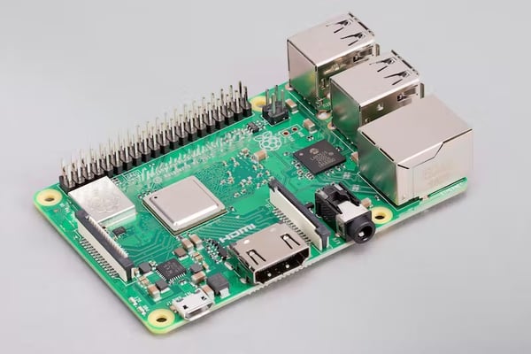
Electronics Cooling is one of the most common uses of Computational Fluid Dynamics (CFD) in industry today. CFD is a software tool which accurately models fluid flow (liquids and gases) and heat transfer (such as Conduction, Convection, and Radiation). One of the most common applications today is for Electronics Cooling, and one of the most popular electronics platforms today is the Raspberry Pi. Raspberry Pi is a low cost, modular, and open format platform that allows designers to build out complex electronics assemblies without having to purchase their own components, or layout their own Printed Circuit Boards (PCB's). One application is to use the Raspberry Pi to build a "retro gaming console", known as the RetroPie. This case study walks through a natural convection analysis of a RetroPie assembly using the Raspberry Pi 3 B+.
RESEARCHING THERMAL LOADS & DATASHEETS
Before any modeling begins, research must be conducted on where the heat is generated on the PCB. Our research led us to the fact that most of the heat is generated by the Broadcom, P/N BCM283780. This System on Chip (SoC) is the "brain" of the Raspberyy Pi 3 B+, and includes the Central Processing Unit (CPU), memory, and various Input/Output channels (I/O's).
After some research and analysis we decided to apply a wattage of 3.5 Watts. This is difficult to verify since the Raspberry Pi 3 B+ utilizes a Thermal Management system which tracks the internal junction temperature of the SoC, and begins to throttle back the frequencies of the ARM Cores. This model does not take that active control into account, rather the thermal load was simplified to a steady state load, and the datasheet junction temperature of 125°C was referenced.
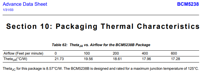
As is often the case, buried in the back of a long pdf datasheet, is a small table that explains some of the most critical thermal information needed for an accurate thermal analysis - the Thermal Resistance and Max Junction Temperature of the SoC. In fact, the datasheet of the Raspberry Pi SoC is not readily available, and so these numbers came from a similarly manufactured Ball Grid Array (BGA) component from Broadcom.
CREATING THE RIGHT "LEVEL OF DETAIL" IN THE CAD MODEL
One of the "classic" problems we have in Computer Aided Engineering (whether for structural or fluids simulation), is the need to defeature the CAD file. In this case, where the Inventor model has the fully detailed weldment (needed for structure analysis) that detail is not needed in CFD. It's not the geometry detail that is our focus (we want to keep that!) but rather the computational "weight" of the model.
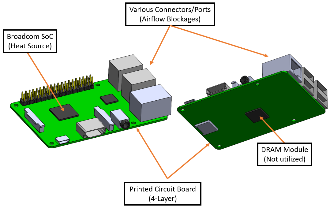
For PCB's, there are a few different ways to model them, based on the level of detail required. In our case, we simplified the board to a single volume in CAD, and then calculated the appropriate equivalent conductivity. The board was measured at .047" thick. Assuming that it is a standard 4-layer board, made from composite layers of FR4 and copper, this results in equivalent conductivity, Keq, values of 21.3 W/mK "in-plane" and 0.35 W/mK through the board.
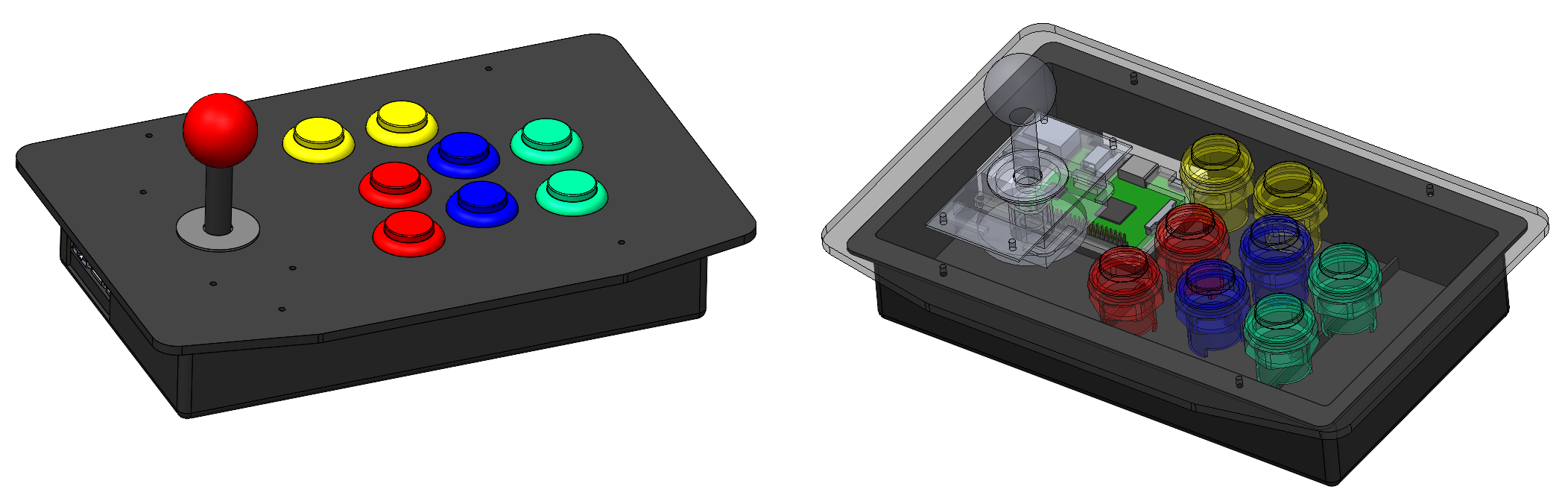
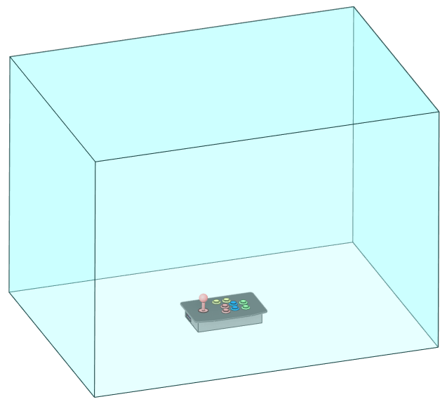
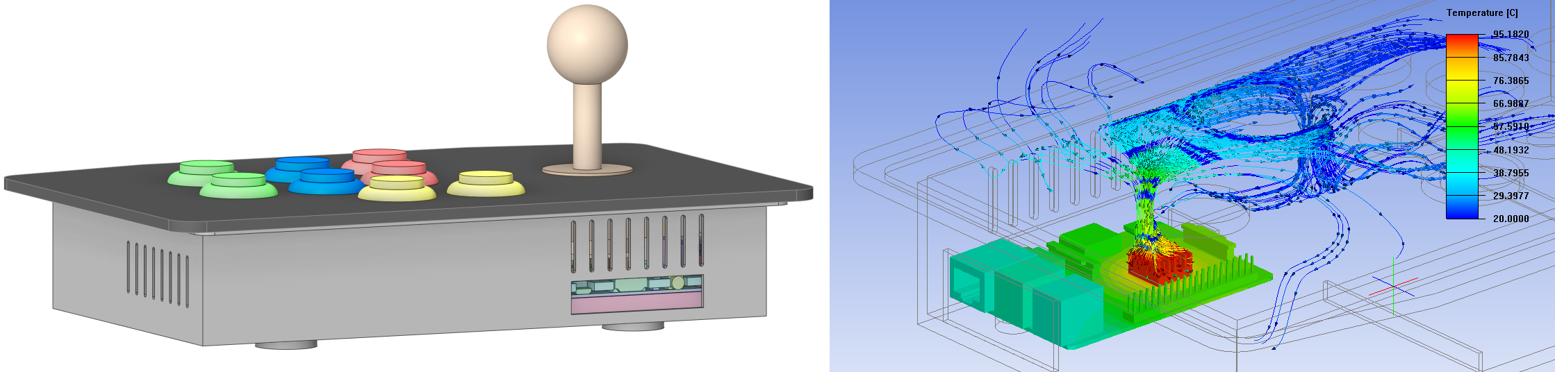
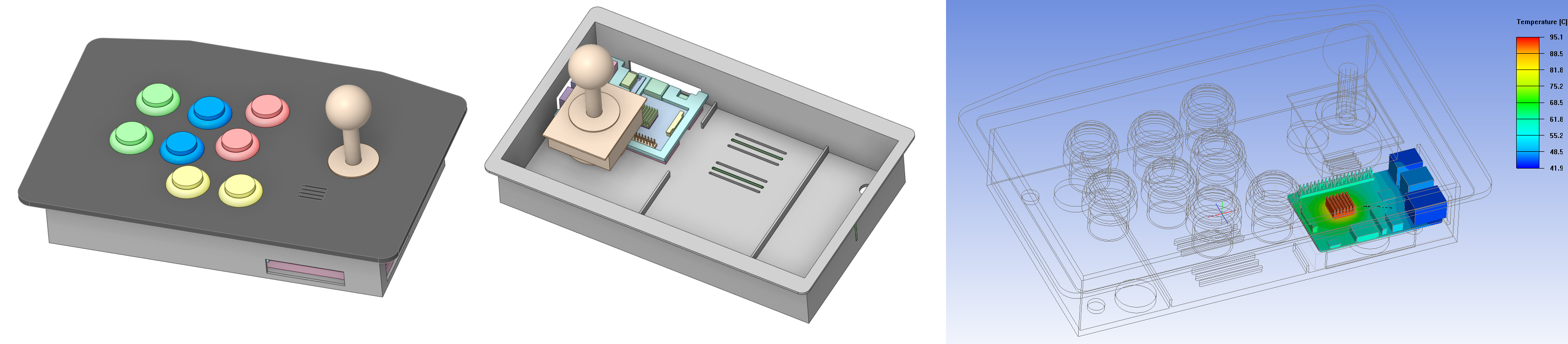
Once the PCB level of detail is established, it can be assembled to the rest of the parts. In the case of the RetroPie, the "next higher assembly" includes the project box, buttons, and joystick assembly. The cables have been omitted because the added detail is not necessary. The additional CAD modeling wouldn't take too long, but the meshing would, and looking at the volume of air in the box vs. the volume/cross section of cables should not impact the airflow that much. If this were a tightly packed box with many cables that impact local velocities and the overall flow impedance, then they would need to be included for accuracy.
The last piece of the puzzle is creating the "box of air" around the assembly to allow for the proper formation of a natural convection "plume". Without knowing how big the plume was going to be beforehand, the box was oversized by about 2x-3x "Widths/Lengths" and about 10x "Heights" tall as shown below.
SETTING UP THE CFD MODEL
This "Conjugate Heat Transfer" CFD model will simulate conduction, convection, and radiation along with corresponding airflow. There is no fan being simulated, so the convection in this case is "natural" (or "free"), and relies on the lower density of the hotter air rising out of the assembly to create a "plume", similar to that which is seen on a match flame or fire. The boundary conditions needed for Natural Convection are quite simple - all boundary "walls" are open, with the exception of the bottom. This will accurately model the RetroPi assembly as if it were sitting on a table. The ambient temperature used for this analysis was 20°C.
At Fastway, we are always striving for a mesh independent solution, and every analyst should do this. Therefore, early simulations start relatively coarse, and tighten up as we review the results and how the airflow looks. If the walls of the analysis are too close to your flow impedance, then it will start to "squeeze" the flow, and create additional error into the analysis (yes, this is true even if you use the slip/symmetry condition). If the analysis volume is too large, then you just end up waiting too long for results.
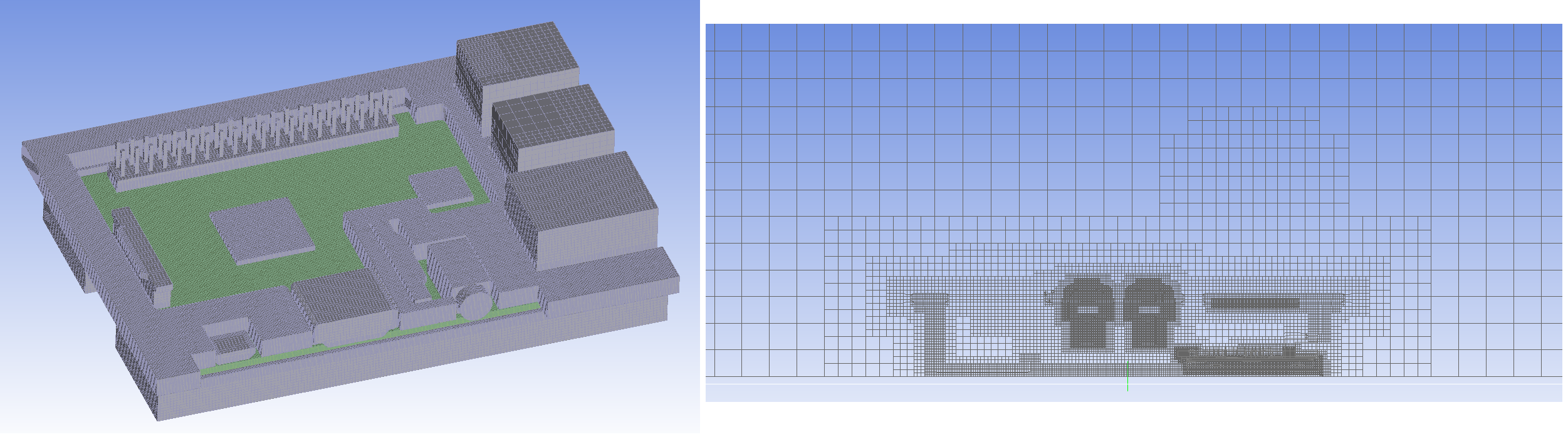
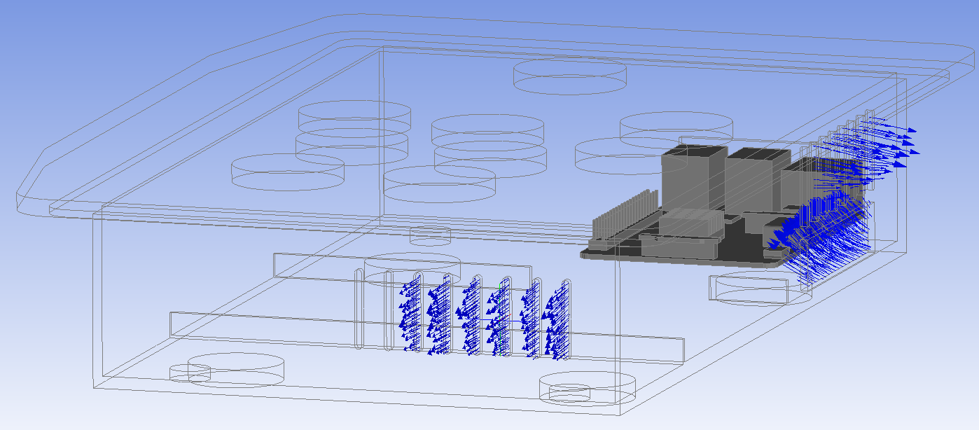
For thermal accuracy, we added a tighter mesh at the PCB (to capture the heat flux from the SoC) as well as any impedances near where the air plume forms (connectors & pins on the board, and the buttons). Shown above are the hexahedral cells of the PCB assembly (left) and a cross section of the cut cell grid (right).
THE CFD RESULTS
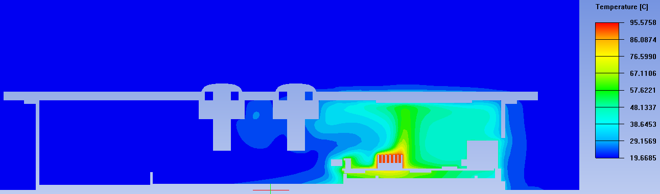
First, we look at the temperature of the entire assembly, and then we review the thermal profile of the Raspberry Pi itself. The first thing we notice is the elevated temperature contained within the project box, near the PCB, and the fact that none of that heat appears to be getting out into the surrounding air.
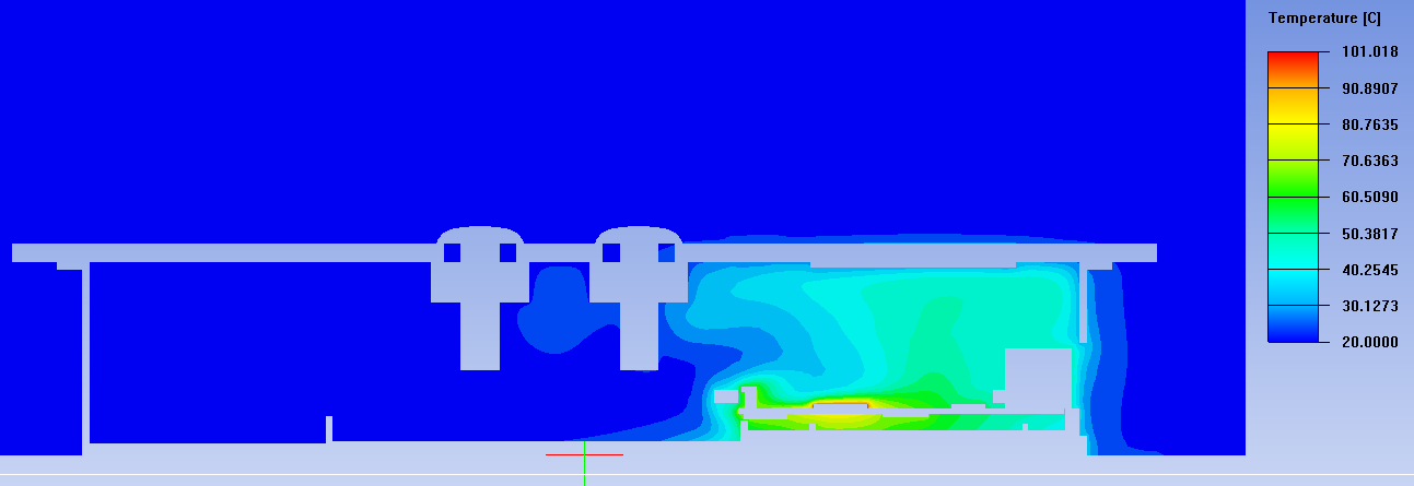
Looking further at the faces of the PCB, we can see a typical heat distribution where the SoC is the hottest, and the heat transfer conducts through the rest of the components towards the
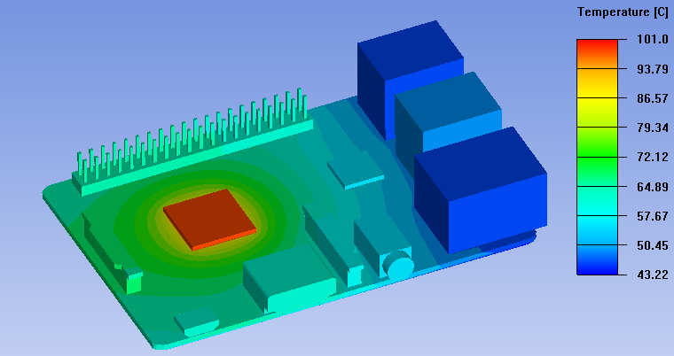
Here we can see the max "case temperature" (the outer surfaces of the component which can be easily measured with a thermocouple or IR camera) of the SoC is 101°C. Using the thermal resistance (Theta Jc) from the datasheet, we calculate a junction temperature of 131.1°C. The manufacturer states a 125°C maximum junction temperature, so let's make some minor (and inexpensive!) changes to the design of the assembly to try and reduce that number, and thus increase the reliability of the design, which for many products also keeps it under warranty.
ADDING A HEATSINK
A very common change to make is to add a heatsink directly onto the top of the SoC. Heatsinks are mass manufacturer in standard sizes so they are quite inexpensive, however the installation process typically includes thermal paste, and therefore the labor cost is relatively high. When we add a heatsink, we see the case temperature drop 5.4°C to 95.6°C, which results in a junction temperature of 125.7°C.
By reviewing the temperature profile, we can see the heat being removed by the heatsink. However, the project box enclosure has no openings, so ultimately the hot air is unable to escape, and this prevents our junction temperature from decreasing even further, down into the allowable range. We could add a larger heatsink, but that is the slippery slope of increased costs!
ADDING SIDE VENTS
Sometimes adding holes to the enclosure around your electronics is not allowed, due to the Ingress Protection Code (IPC) Rating (more info on IPC codes here), but in our case this device will spend it's life in the living room, which is typically a dry, humidity controlled, environment. Additionally, adding holes to the box is nearly "free'", because it does not significantly impact the cost of the design. Here we chose to add side vents with an intended outlet near the PCB, and an inlet on the other side of the project box).
As you can see above, the SoC case temperature drops to 95.2°C, which results in a Junction Temperature of 125.3°C. However, we location of the vents is not ideal. As shown on the top right, the hot air leaving the heatsink does not make its way over to the outlet, in fact it just recirculates inside the box, and thus the side vents are not very impactful. Looking into the vents in deeper detail below, we do see the "inlet" vents (left) are actually acting as outlet vents and the "outlet vents" are acting as an inlet/outlet.
ADDING TOP VENTS
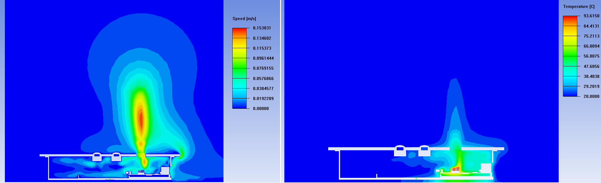
Finally, we add vents in the best location - allow the heat to be removed by adding top vents. This finally brings our case temperature down to 93.6°C, which results in a final junction temperature of 123.7°C!
Looking at the velocity below, we can now see the plume of air being allowed to leave the enclosure straight up. When this is allowed, the plume builds momentum, which increases the airflow, which increases the heat transfer rate, which cools the SoC even more!
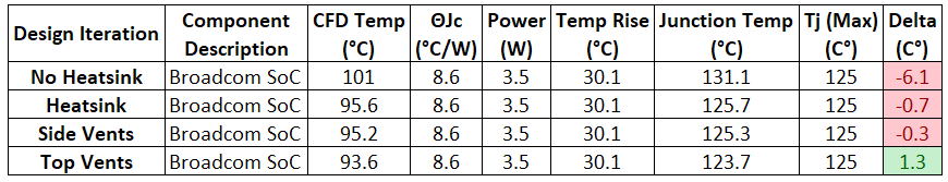
Looking back on this entire investigation, here is a table of the design iterations, and their performance comparison:
NEXT STEPS
Additional design changes that could further reduce the Junction Temp, and increase reliability are: Change board design (more copper, add thermal vias, etc), larger heatsink and vents, or of course we an always add a fan. These design changes each have there own cost/benefit ratio that should be assessed.
If you would like to learn how to do this yourself, or are interested in having us perform an electronics cooling simulation on your design, please contact us using the button below!