One of the key benefits of Additive Manufacturing (AM) technology is the ability to create geometry that is nearly impossible via other manufacturing methods. As a result, Computer Aided Design (CAD) tools are producing advanced geometries, such as Lattice Structures, that must be specifically designed for their application. One such application is a heat exchanger, which is designed to optimize heat transfer across the interface of two working fluids. This case study walks through an example lattice structure's fluid performance (velocity, pressure ,etc.) using Computational Fluid Dynamics (CFD).
Quick Overview of Lattice Structures
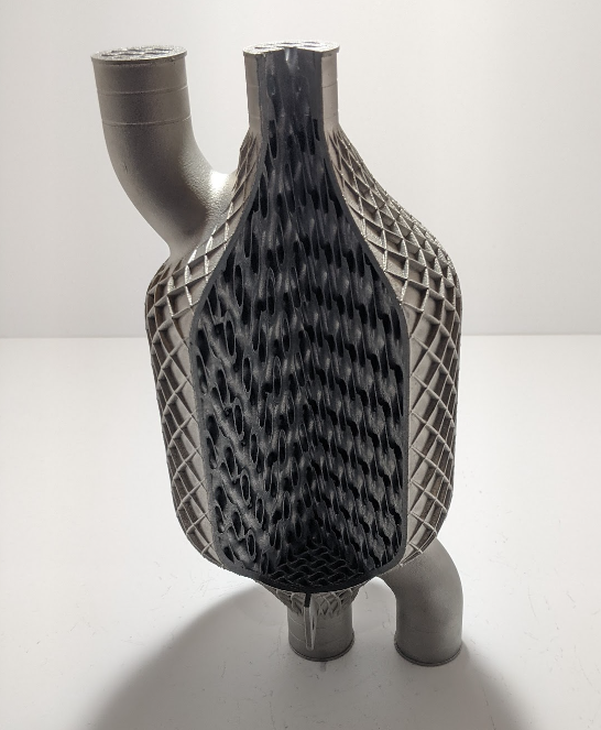
With advancement of Metal AM processes, lattice structures are being utilized for fluid heat exchangers, such as gas-to-liquid, and liquid-to-liquid application. This is due to the unique characteristic that lattice structures, have a high surface area to volume ratio, allowing for efficient convective heat transfer. Below is an example that we found at the most recent International Manufacturing Technology Show where Oqton was showcasing their Implicit Modeling Capabilities.
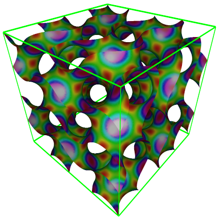
There are many styles of Lattice structures, however, of particular interest is the family of Triply Periodic Minimal Surface (TPMS) geometries, which are known for their minimal surface area for a given boundary. This is advantageous as it creates an efficient boundary wall between, for example, two separate fluid volumes. Examples of various TPMS's are shown in the graphics at the top of the page. Many heat exchangers are designed to withstand "harsh environments", such as the shock and vibration associated to aerospace and automotive applications. Therefore, a second consideration is the robustness of the structure. Within that family, the Gyroid shape is effective because it maintains quasi-isotropic structural properties, such as Modulus of Elasticity and Poisson's Ratio. The example below shows the Gaussian Curvature of a Gyroid Structure (courtesy of Wikipedia).
Due to the advantageous thermal and structural characteristics, the gyroid will be analyzed for fluid properties.
Challenges in Modeling Gyroids
One of the main challenges modeling TPMS's such as gyroids, is that many CAD software programs have difficulty regenerating them as a traditional "watertight" CAD volume. Discussing why this occurs is a topic for another article, but it means that today a workaround must be used in order to get a CAD model that is "meshable" for downstream CFD analysis. The workflow presented here uses Ansys SpaceClaim, which creates the gyroid using faceted geometry (think: STL filetype) which can then be solidified into a CAD model (think: stp/iges filetypes).
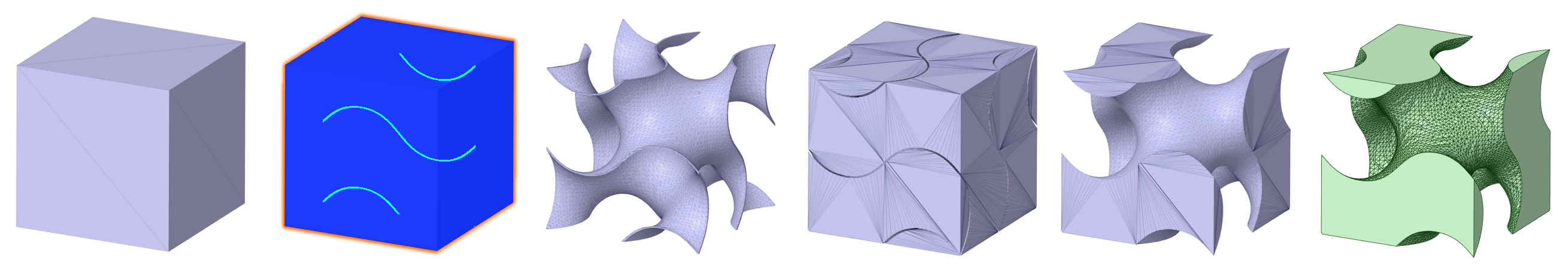
These "solidified" models can be difficult to manage due to the high surface face count. For the workflow above, a faceted cube was shelled using the lattice feature, and then boolean operations were used to extract one of the two fluid volumes which was then solidified for analysis. To test out how difficult it is to manage these complex surfaces, this study focuses on a characteristic "unit" cube that has a 1x1 Gyroid infill as well as a 2x2 as shown below.
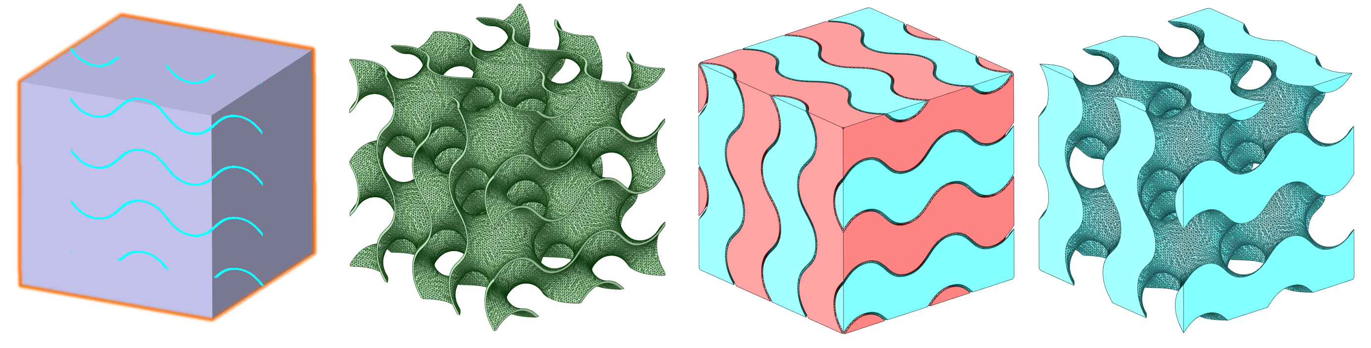
Using the same starting "unit cube", and dividing the wavelength of the gyroid in half, the workflow is repeated to create the single 2x2 fluid volume for subsequent CFD analysis in Fluent.
MESHING GYROIDS
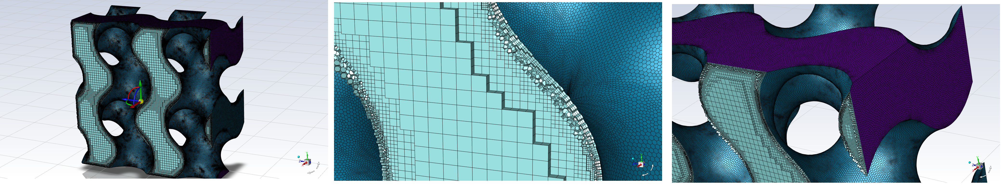
With the geometry solidified, it can now be prepared for CFD analysis via a meshing task. It is critical to the accuracy of the CFD model that the mesh size by small enough to capture the curvature of the gyroid walls, so fluid separation from the wall is accurately predicted if present in the flow.

Once the surface meshing is done, the volume meshing is quite easy. In our model, we specified the default value of 3 inflated boundary layers, with a first layer height of 0.2 mm. Coupled with the poly-hex core method, which puts high quality polygons on the surface, inflates them through the boundary layer, and then transitions to perfect hexahedra in the free stream away from the wall... to minimize numerical error due to low quality elements. Using the orthogonal quality metric, we maintain a value greater than 0.1 to prevent any mesh quality-induced divergence.
With the high-quality mesh complete, a range of flow rates are setup at the inlet, and the walls are defined on the faces normal to the inlet/outlet. The flow rates are described as a function of the length of the "unit cube", so the units below are shown in Lengths per second (L/s).
THE CFD RESULTS
The first thing to review is the Y+ value, so we can assess the potential error in our turbulence model. Here we see that with a velocity of 1 L/s we have an average Y+ value of ~2, and a max Y+ ~5, which should work well with our K-Omega SST Turbulence Model.
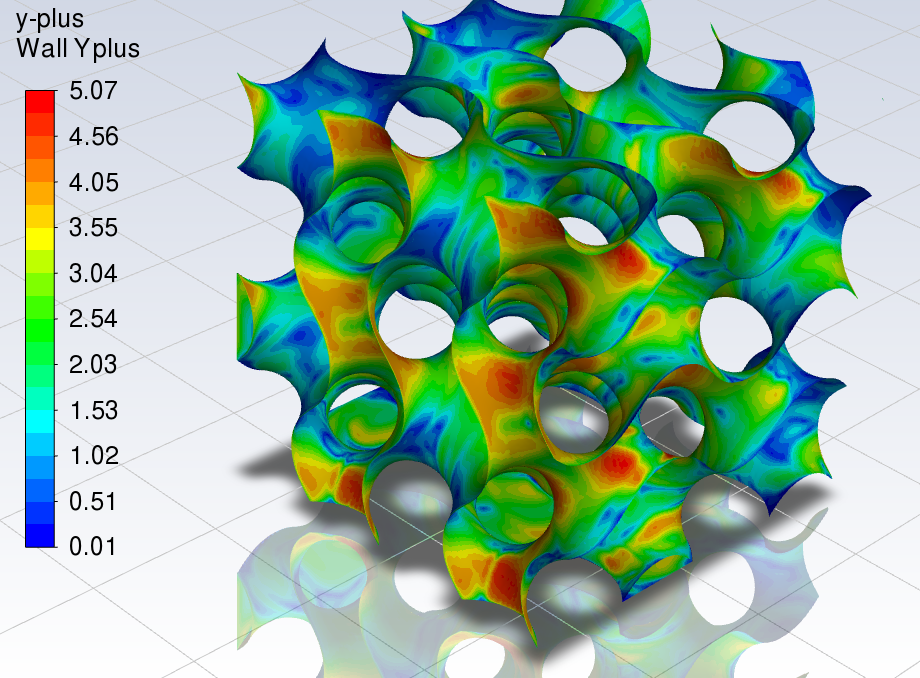
Our entire investigation actually swept through a range from 0.1L/s to 10L/s. When we review the y+ for the entire range, the y+ value is 1 and 32, which is acceptable.
Now that we have confidence in our mesh, the first thing to review is the velocity. For this, we chose to use iso-surfaces of X-Velocity (the primary flow direction normal to the inlet plane) at 67% of max velocity, as shown below in the 0.1L/s flow case:
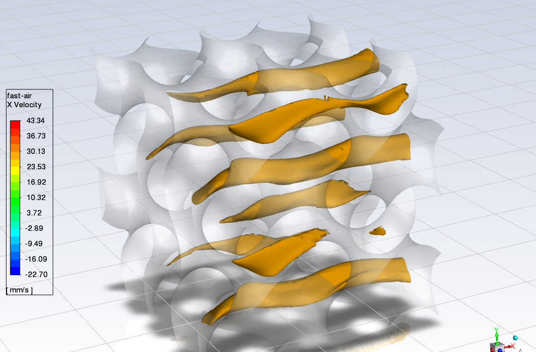
Note that this velocity (67% of max) is present al the way through the lattice structure form inlet to outlet. When all flow cases are compared to each other, we see a trend that the peak velocities are localized closer to the inlet as we get to the higher flow cases of 5 L/s and 10 L/s.
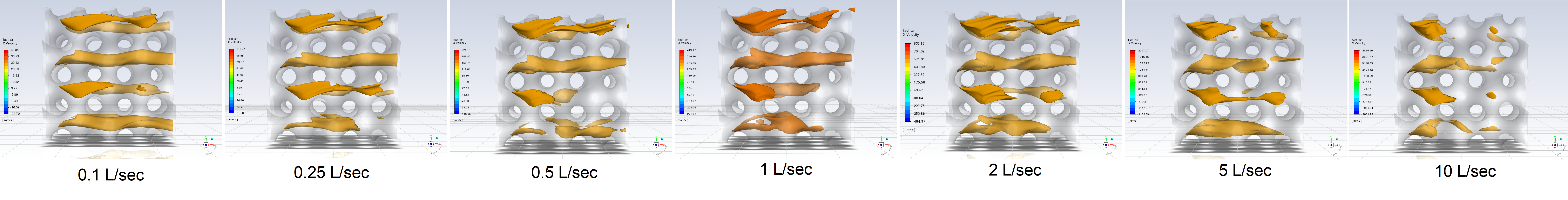
This is most likely a violation of St. Venant's Principle (the inlet velocity vector is constrained to the surface normal), but it is certainly something to consider when designing heat exchangers, as the flow will ultimately have to come in from a single inlet entry point, and corresponding flow inefficiencies will be present.
Of course, one of the key parameters of the design of a heat exchanger is to understand the pressure drop, as this is critical in designing the entire system (fan/pump operating curve, power input, etc.). Below is the trend of pressure drop from each flow case of 0.1 L/s, 0.25 L/s, 0.5 L/s, 1 L/s, 2 L/s, 5 L/s, and 10 L/s, with the peak velocity as a multiple of inlet velocity for reference.
| Parameter: | 0.1 L | 0.25 L | 0.5 L | 1 L | 2 L | 5 L | 10 L |
|
Pressure Drop [Pa] per Meter
|
9 | 46 | 172 | 634 | 2270 | 12312 | 38797 |
|
Max Velocity [Multiple of Inlet Vel.]
|
4.3 | 4.6 | 4.4 | 4.2 | 4.2 | 4.5 | 4.6 |
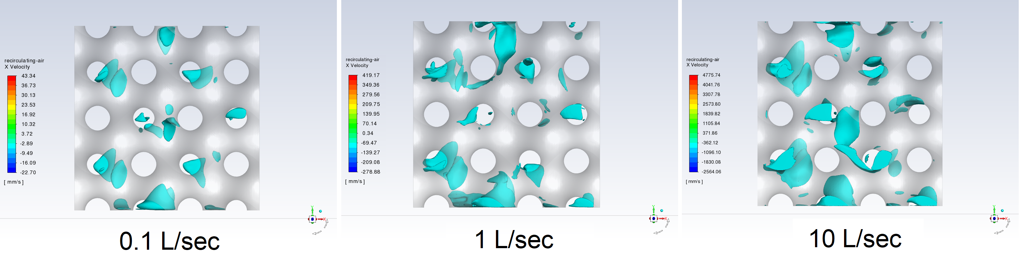
One of the key contributors to pressure drop through internal flow is the presence of turbulence, especially separation of the boundary layer from the wall, which can often lead to recirculation (or "backflow"). Recirculation in a heat exchanger is bad because it lowers the overall efficacy of the pump (a situation that arises when the actual flow rate is lower than the theoretical) and can create hot spots as well, which can lead to reliability issues.
CONCLUSION & NEXT STEPS
In this investigation, we learned about the opportunity in designing for additive manufacturing using a 3D Printed Lattice Heat Exchanger. We uncovered some pretty big challenges in geometry creation, CAD preparation, and file management. There is certainly a lot more investigation required here such as inlet/outlet optimization, wall/edge effects. From a CFD modeling standpoint, stay tuned for further analysis including the addition of a second fluid, and adding it heat transfer to complete the total physics involved.
If you would like to learn how to do this yourself, or are interested in having us perform analysis on a 3D printed lattice structure, please contact us using the button below!