In many manufacturing-related industries, Mechanical Engineering Simulation tools (like Finite Element Analysis and Computational Fluid Dynamics) are used as an aid in product development. They are used in various design phases to predict baseline performance specs, design around potential failures, and establish warranty strategies.
Realizing the benefits of these tools depends on several factors, including the capabilities of the Engineering team, the complexity of the product, and the volume of production. As a result, the return on investment of FEA & CFD software varies from industry to industry. A recent trip to the United Arab Emirates highlighted opportunities for contemporary engineering practices in a very traditional place.
Slow to Adopt
Traditionally, Architecture, Engineering and Construction (AEC), has had a slower adoption rate of engineering simulation software when compared to other manufacturing-based industries, such as Aerospace and Automotive. We believe there are a number of potential reasons for this:
- A "Build Quantity" of One - Every building in the world is unique. As a result, there is a limited amount of knowledge you gain from the simulation of a building, which can be leveraged for the next one. As a result, the time invested to build the models cannot be leveraged on subsequent simulations.
- Many Teams with Many Goals - A building is much more than just a single system. It is truly a system of systems. In many cases these systems are designed by separate teams, each with their own separate goals in mind. Unfortunately, a lack of efficient communication can result in a lack of alignment with respect to design and analysis techniques.
- Size & Complexity - The "aspect ratio" of a CAD model is the ratio of the largest dimension divided by the smallest dimension. For buildings (especially very tall ones like the Burj Khalifa pictured below), this is unbelievably high. As a result, the simulation model must be simplified to keep computing requirements economical. This means more time spent on pre-processing, and a higher cost-per-analysis.
- Design by Rule - Many designs decisions in Construction Engineering are made using standard hand calculations, such as for beams, columns, and concrete. These calculations, as exercised during the "Professional Engineer" certification test have worked perfectly fine for generations of prismatic, rectangular buildings, and thus the need for FEA has been quite low. In addition, simple (conservative) wind calculations can be made with paper and pencil, negating the need for CFD. However, architectural design trends are pushing buildings towards more complex and efficient shapes.
- Design for Adjustment - One might think buildings are static, but in fact they are very dynamic. In a way, they act like tall living, breathing machines, that live for a very long time! As a result, they must be built for adjustability, to account for changing environmental conditions and use cases overtime. With adjustability in mind, an "optimized" design is not necessarily a design outcome. Since FEA & CFD tools excel at providing optimized designs given a set of design inputs, their value may not be recognized as readily.
- Long Design-Build Cycle - Buildings can take years, or even decades to build, including large teams of people who come and go along the lifecycle of the project. Comparatively speaking, FEA and CFD tools are designed to be deployed in matter of hours/days (our seconds/minutes in the case the new generation of web-based tools). Without a sense of urgency, perhaps deploying "highly sophisticated" tools, may not be regarded as a necessary expense.
- Design-Build Differences - FEA and CFD tools are best used alongside precise CAD data which is being created during the critical path to production. In most contemporary manufacturing processes, differences between CAD data and manufactured parts are thousandths of an inch. However, in construction tolerances are measured in inches, or even feet, depending on the application. As a result, FEA/CFD simulations may be drastically wrong when compared to actual measured values, simply because the geometry was built different than what was designed in CAD.
Quickly Adapting
Despite these potential reasons for slow adoption rates, simulation is being deployed in the AEC market more and more. As mentioned above, many buildings are large and complex structures that are simultaneously static and dynamic. A building is both a fixed structure but those that occupy and use the building also turn it into a functional object. Simulation can be used to make the structure more aesthetically pleasing and functional for those who occupy the space inside and outside. Listed below are some example mechanical engineering simulations applied to Architecture and Construction:
Structural Analysis
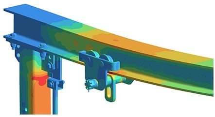 Static Analysis of a Bolted Structure in Detail (Courtesy of Altair/Simsolid)
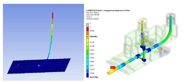
Static Analysis of pressurized Pipes (Courtesy of Ansys)
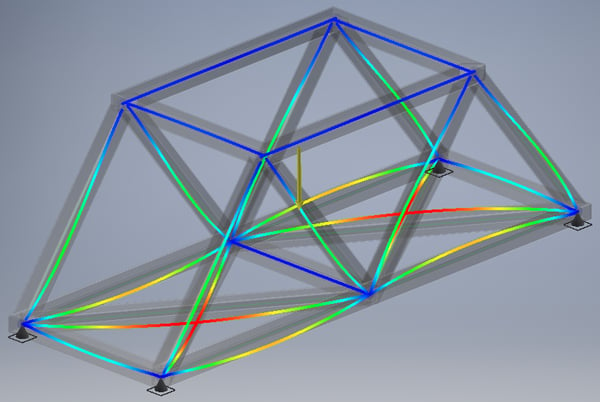 Modal Analysis of Beam Structure (Autodesk FEA; courtesy of Fastway Engineering)
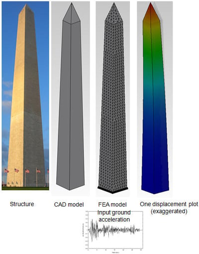
Dynamic Analysis of Seismic Activity (Courtesy of Solidworks)
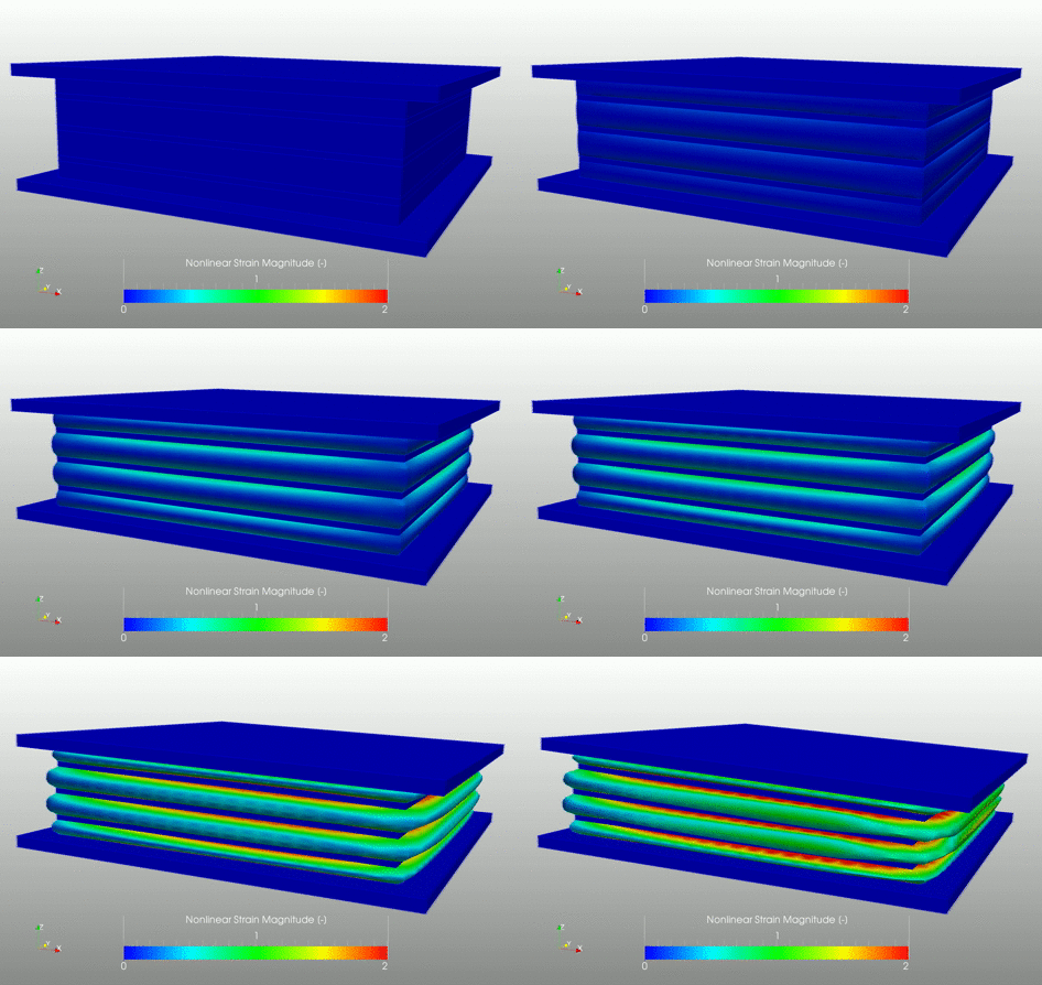 Nonlinear Analysis of an Elastomeric Bearing Pad for a Bridge (Courtesy of Simscale)
Fluid Analysis
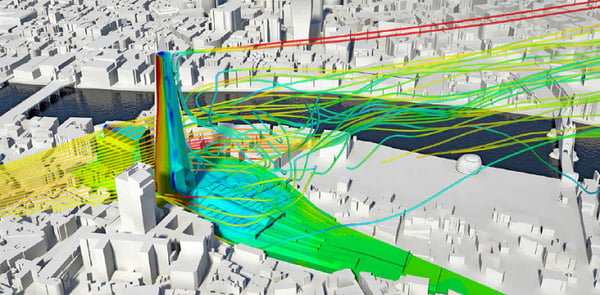 Wind Loading on a Building (Courtesy of Siemens/CD-Adapco)
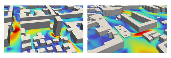 Wind Velocity and Pedestrian Comfort (Courtesy of Simscale)
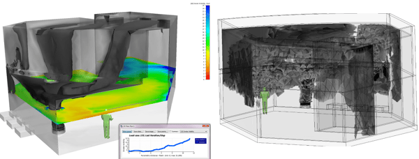 Air Quality and Smoke Visibility (Courtesy of Autodesk CFD)
Thermal Analysis
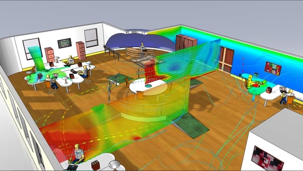 HVAC/Occupant Comfort (Courtesy of Mentor/FloEFD)
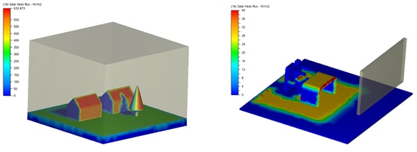 Exterior (L) and Interior (R) Solar Radiation Levels (Courtesy of Autodesk CFD)
Fast Growth in the Middle East
On a recent trip to the Unite Arab Emirates (UAE) , we visited two cities that have seen fast population growth in the last few decades: Dubai & Abu Dhabi. When the population grows, so do the buildings! In fact, Dubai boasts 12 of the 50 tallest buildings in the world, including the Burj Khalifa, which is the tallest at 2,723 ft tall. Abu Dhabi is also home to the Burj Mohammed Bin Rashid, which is the the 33rd tallest. Enjoy some of the beautiful pictures below and just imagine what kind of simulation is utilized to ensure these buildings are as safe and comfortable as they are tall and beautiful!
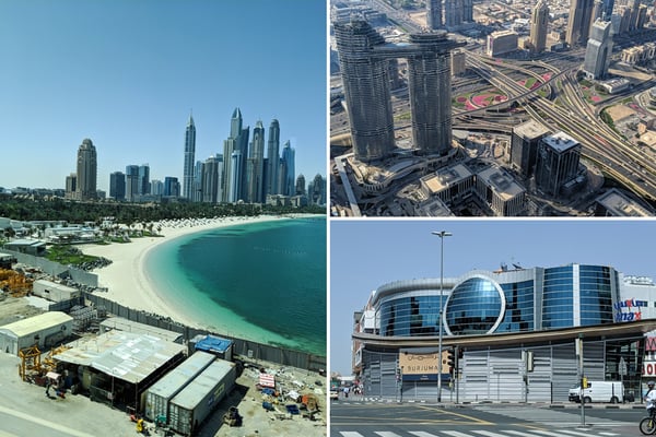 Clockwise from left: Dubai infrastructure along the Dubai Marina, beneath "The Burj", and at the BurJuman Mall.
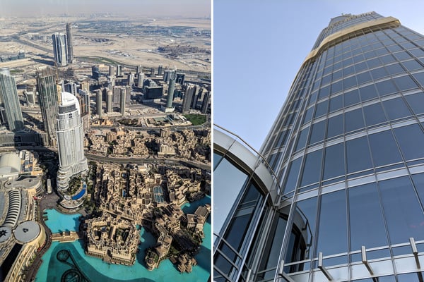 Contrasting constructions: Glass and steel looking down on concrete cities
 The pinnacle of all buildings: The Burj Khalifa at dusk
Think simulation can help your team build taller, smarter buildings in less time? Click below to learn more about Fastway Engineering's intro and advanced FEA/CFD training classes in a wide variety of the most popular simulation software brands.


