If you’re like me, you are an engineer who spends quite a bit of time designing and analyzing parts that shake, vibrate, or rotate. Because, in our world, everything is about the mass-to-stiffness ratio, and fine tuning the resonant frequencies of our designs. Long gone are the days of prototyping iterations on a shaker table with a strobe light. Endless nights in the vibe lab have been traded for hitting [SOLVE] on our computer before bedtime and waking up to hi-res videos of the first 100 modes of our structure. As a result, the modal analysis is one of our best friends.
 From the laboratory to the laptop, resonant frequencies can be found much quicker and cheaper on the computer. (Electrodynamic Shaker Machine courtesy of Thermotron).
In today’s era of insanely fast paced product releases, designers are constantly looking to shave time off of their R&D process like shaving pounds off of an aircraft wing. The fundamentals of the modal analysis have been the same since the beginning: Clean up the CAD, Mesh, Setup, Solve, and Review. About 50% of the time is spent going back and forth between the CAD and the Mesh, constantly trying to answer questions such as:
- “Do I have enough elements through the thickness?”
- “What is better, a tet or hex mesh? Maybe a mix of both?”
- “Is this radius important, or what about this chamfer?”
- “Do I need to lower the density because I just removed a bunch of small holes?”
- “Did the CG move too much?”

Analyzing production-ready CAD, such as this Mazda Miata crankshaft in Onshape, requires a judgement call: How much detail is enough? Machined components contain dozens of very small but critically important radii and chamfers.
Time is Money
How long does this whole process take? Well, for a single part, the best of us can slim this down to about an hour. The time may be a bit less for a simple part, but probably more for an assembly. This means, we’re spending 30 minutes playing around with the geometry and the mesh.
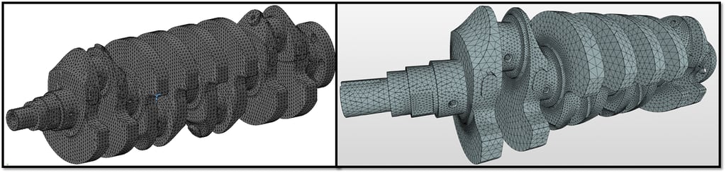
These two “typical” meshes for our crankshaft part have multiple radii and chamfers removed. Left: 210,000 tet elements using local FEA. Right: 923,000 tet elements using cloud-based FEA. From CAD to results took 30 minutes each.
Engineers are expensive employees, and so saving time is very beneficial to our businesses. There are dozens of software companies, and hundreds of applications engineers, like me, who are constantly developing new ways of leaning out this process with tips, tricks, and scripts. In essence, we’re just automating the existing process. To truly speed things up, however, you need to change the process. And that is exactly what SIMSOLID has done.
Solving in Seconds with Meshless FEA
SIMSOLID is best described as "meshless FEA", and it uses a completely new computational engine to solve the problem. The complete explanation can be found on their website (https://www.simsolid.com/white-papers/), but ultimately it decouples the CAD geometry from the FEA mathematics, solves the equations of state, and then maps the results back onto the original geometry. All of this while performing a multi-pass convergence. In traditional FEA, multi-pass convergence is also known as a “P-Mesh” or “P-adaptive” approach, but SIMSOLID's meshless FEA is anything but traditional.
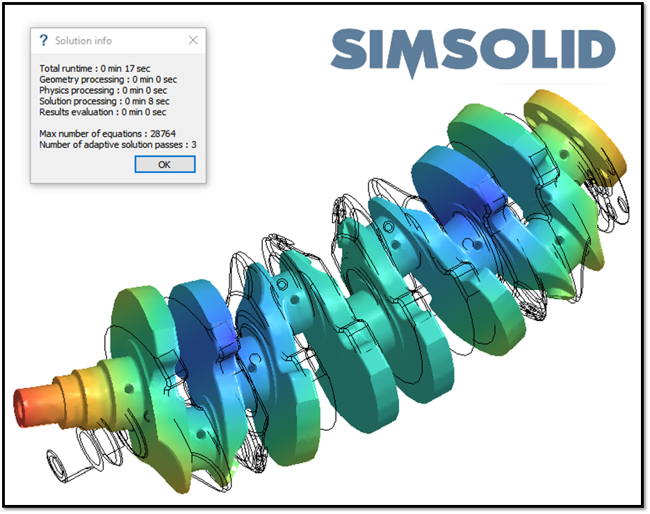
By not using a mesh, like in traditional FEA, SIMSOLID found the first 30 modes of our crankshaft in 17 seconds. So now, instead of analyzing 5 designs a day, we can analyze 500.
So, what does this mean for our FEA workflow? Well, first off, there’s no mesh to babysit. This means that 50% of our time is spent doing something more important. In addition, solve times are drastically reduced, for example the crankshaft above was solved with 29,000 equations. In traditional FEA, this is equivalent to a structural analysis of about 10,000 elements (with 3 DOF). That’s 1-2 orders of magnitude smaller than what we're used to.
The More Parts the Merrier
Additionally, with assemblies it gets even better. With SIMSOLID, there is no need to use Constraint Equations (like RBE3) or virtual springs to connect your assembly together. Just import to SIMSOLID, and solve. Don’t worry about gaps and interferences, because SIMSOLID uses a simple user-entered tolerance for establishing connections. Less button clicks means less potential for error.
 This quadcopter frame assembly has 52 parts, and 1028 connections. SIMSOLID found the first 10 flexible modes in 36 seconds.
In dynamics, and engineering as a whole, every designer out there is trying to learn as much as they can as quickly as they can. Whether it’s to get to production faster, or to try more variations in a given amount of time, speed is the name of the game. Either way, SIMSOLID's meshless FEA represents a time savings that’s an order of magnitude more than anything we’ve ever seen before in traditional FEA. As an engineer that lives in a dynamic world – that really resonates.

Benchmarking shows correlation within 2% for calculating the first mode resonance of our crankshaft. Which one is correct? Only testing can tell us that, but to start, SIMSOLID is the only one which used the full-featured CAD geometry.
Finally, you can view the video tutorial for this crankshaft here:
Want to learn more about how this innovative new software works? Click the link below to learn how Simsolid solves the "Goemetry Problem" and to learn about the mathematical theory behind the Simsolid method.

Not ready to contact us, but still want to stay in touch? Sign up for our newsletter below, and get information on Training Discounts, Industry News, Fun Events, and other smart stuff!